Linear Drive 2.0
- Timothy Bukowski

- Oct 16, 2020
- 5 min read
October 2020
Overview
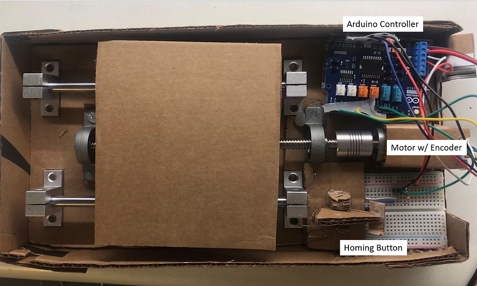
For this project I updated the linear drive which previously used a stepper motor, to now use a dc motor with encoder, which I controlled using a closed loop proportional control. With the stepper motor we could comparatively control the speed the system was moving, but could not define a specific speed to move. The closed loop control in this upgraded system allows us to set a desired movement speed of the carriage and then the system will correct itself until it reaches the desired speed.
Control Theory
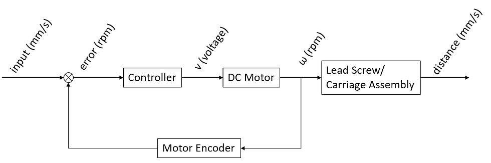
To control the motor we used a closed loop proportional control. An initial voltage is sent to the motor, then the built in encoder measures the angular speed of the motor using a sensor that sends a signal every revolution. The Arduino reads the signal and converts it to angular speed. At this point it calculates the error between the desired rpm and the current rpm. The controller then increases the voltage proportionally to the error, so a larger error leads to a a larger increase in voltage. Conversely if the rpm is too low, then the error will be negative and the voltage will decrease proportionally to the error. This leads to an oscillation about the desired value which you can see in the plots of displacement vs time below. The proportional constant can be adjusted to affect the response of the system and how fast it reaches a steady state.
Circuit
Code
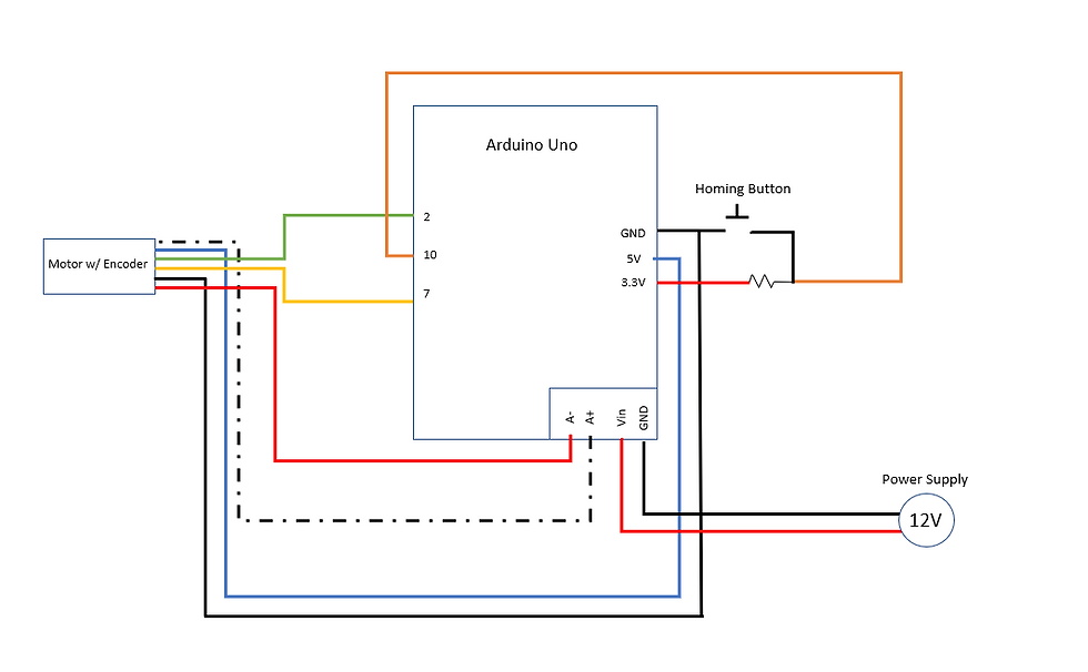
The code was similar to the code use for the linear drive with the stepper motor. However, this time we didn't have to manually switch the coil directions, we only had to set the direction we want the motor to spin (pin 12) and the speed, which is set by voltage (pin 3). To read the encoder we used the interrupt pin 2 to read on of the encoders, so that it would read the pin every other command, which is important because the motor is spinning fast, so if it were to use a normal pin, it would miss rotations. The second encoder is on pin 7. Having two encoders allows us to interpret the direction of the motor based on the order that they send signals.
For the homing sequence we made a function goHome() which has an input of speed in mm/s. The speed is converted to rpm, an error is calculated and the control loop begins. The loop runs until the homing button(pin 10) is pressed.
I also made a moveT0 function. This function has inputs for distance, speed, and direction. This works very similarly to the goHome function, however, instead of running until the button is pressed, it moves a desired distance. This distance is set by the number of steps of the motor which we can calculate since we know the number of steps per rotation of the motor and the rotations per millimeter of the screw.
Outcome


On the left is the plot of the linear displacement vs time and velocity vs time of the homing sequence. I ran a homing sequence that consisted of:
The switch is pressed to begin the sequence.
After a one-second delay, the carriage begins to move towards the switch at a speed of 20 mm/s.
The switch detects contact with the carriage.
The carriage retracts 5 mm from the switch at a speed of 5 mm/s.
The carriage stops and moves towards the switch at a speed of 5 mm/s. The carriage stops and moves away 30 mm from the switch at a speed of 5 mm/s.
The displacement is set to zero after the initial homing sequence. The velocity jumps at around two seconds as the voltage is still high from when the motor was at 2o mm/s on the first homing sequence. Then it drops and overshoots 5 mm/s, but almost levels out before reaching home the second time. In the last section, we can clearly see the effect of the proportional control. The speed overshoots by 100%, then begins to oscillate about the desired value of 5 mm/s.
Code
void setup() {
attachInterrupt(digitalPinToInterrupt(2),count,RISING); // Set digital pin 2 to trigger interrupt function
// count() when a rising flank is detected.
// Encoder A connected to pin 2
pinMode(7,INPUT); // Encoder B on pin 7
pinMode(10,INPUT);// Homing button
pinMode(12,OUTPUT); // Coil A: DIR
pinMode( 3,OUTPUT); // Coil A: VOLTAGE
pinMode( 9,OUTPUT); // Coil A: BREAK
digitalWrite(9,LOW); // Disable break
Serial.begin(115200);
}
volatile long int pulses=0; // Pulses measured by encoder since start of program
float target=0; // The r.p.m. we want to reach
double v_motor=0, current_rpm=0; // Control voltage, from 0 (min) to 255 (max)
float error=0; //
float kp=.5; //Proportional Control Gain
float correction=0;
void loop() {
// Set the direciton of rotation (if already set, no need to repeat
while(digitalRead(10)){} //Switch is pull up, goes to LOW when pressed
delay(1000); //delay to let you move your finger
//Send drive home
Serial.println('1');
goHome(20);
Serial.println('2');
moveTo(5,5,1); //Move 5mm at 5mm/s
Serial.println('3');
goHome(5);
Serial.println('4');
moveTo(30,5,1); //Move 30mm at 5mm/s
shutdown_all();
while(true);
}
void goHome(int spd){
//send drive to home position(input speed in mm/s)
digitalWrite(12,HIGH); //Set direction
target=spd*60/8; //Target speed in rpm
while(digitalRead(10)){
error=target-current_rpm; //*****May want to initialize current_rpm to 0, prob doesnt matter tho*******
// Serial.println(error);
correction=kp*error;
// Serial.println(correction);
v_motor=v_motor+correction;
//Serial.println(v_motor);
// Make sure v_motor is within 0-255
if (v_motor>255) // Limit vout to 0<=vout<=255
v_motor=255;
if (v_motor<0)
v_motor=0;
// Output voltage to motor, wait for it to respond and measure new speed.
analogWrite(3,int(v_motor)); // Feed voltage to motor. v_motor has to be recast into an integer
delay(100); // Wait for motor to reach new speed (you can change this)
current_rpm=getSpeed(10000); // Measure speed using 100000 us of data (you can change this)
// Print out Time [us], Control voltage [0-255], Speed [r.p.m.]
Serial.println(String(millis())+"\t"+String(int(v_motor))+"\t"+String(current_rpm)+"\t"+String(pulses));
}
pulses=0;
}
void moveTo(int dist, int spd, int dir){
//Move desired distance in mm at spd in mm/s
//dir=1 is positive direction, dir=2 is towards home
if(dir==1) digitalWrite(12,LOW); //Set direction
else digitalWrite(12,HIGH);
target=spd*60/8; //Target speed in rpm
float n=dist*374/8; //Number of pulses to move desired distance
current_rpm=0;
while(abs(pulses)<=n){
error=target-current_rpm; //*****May want to initialize current_rpm to 0, prob doesnt matter tho*******
// Serial.println(error);
correction=kp*error;
// Serial.println(correction);
v_motor=v_motor+correction;
//Serial.println(v_motor);
// Make sure v_motor is within 0-255
if (v_motor>255) // Limit vout to 0<=vout<=255
v_motor=255;
if (v_motor<0)
v_motor=0;
// Output voltage to motor, wait for it to respond and measure new speed.
analogWrite(3,int(v_motor)); // Feed voltage to motor. v_motor has to be recast into an integer
delay(100); // Wait for motor to reach new speed (you can change this)
current_rpm=getSpeed(10000); // Measure speed using 100000 us of data (you can change this)
// Print out Time [us], Control voltage [0-255], Speed [r.p.m.]
Serial.println(String(millis())+"\t"+String(int(v_motor))+"\t"+String(current_rpm)+"\t"+String(pulses));
}
}
void count(){
// This funciton is executed whenever a rising pulse flank is detected on pin 2 (Encoder A)
if (digitalRead(7)==HIGH)
pulses--;
else
pulses++;
}
double getSpeed(long int us){
long int t0=0, initialPulses=0, delta_pulses=0, delta_t;
double rpm=0;
initialPulses=pulses; // Set initial pulse count
t0=micros(); // Set initial time, in us
while(micros()-t0<us){} // Allow sampling time (us) to elapse
delta_t=us; // Duration of the sample, in microseconds(passed as argument)
delta_pulses=abs(pulses-initialPulses); // Pulse increase during sample period
rpm=double(delta_pulses)*1E+6/double(delta_t) /374.0 * 60.0; // w=d(theta)/dt, convert to r.p.m.
// Encoder gives 374 pulses/rev
return(rpm);
}
void shutdown_all(){
digitalWrite(12,LOW);
digitalWrite(3,LOW);
}


Comments