Electric Screwdriver Reverse Engineering
- Timothy Bukowski

- Dec 12, 2018
- 4 min read
Updated: Feb 17, 2020
December 2018
Overview
In this project we reverse engineered the Black & Decker Li2000 screwdriver. We hoped to learn more about gear ratios and how you can it can be taken advantage of to drastically increase torque of object. We also were able to get practice with computer automated design (CAD) and modeling and drawing objects. Most importantly we also came into this project hoping to learn how an electric screwdriver works.

Gearbox Analysis
Gear Ratio

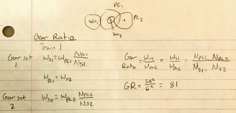
I was able to find the gear ratio using the number of teeth of each gear in the system. The combination of four kinds of gears, the sun (s), planets (p), planetary carriers (pc), and ring (r) create a gear ratio of 81. With this we can find that the torque output of the screwdriver will be 81 times that of the motor used for power. In exchange, the screwdriver will spin 81 times slower than the motor.
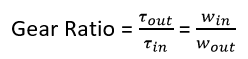
Pitch Diameter
I was easily able to measure the distance from the outside of the pins, and from this I could find the center to center distance of the planet gear to sun gear

With the center to center distance (d) I could find the rest of the pitch diameter, which is the the diameter of the gears which make contact with each other.
The B&D Li2000 uses this epicyclic gear train because it allows it to get a large gear ratio within a small volume. The planetary carrier of this kind of train can act like another imaginary gear whose number of teeth is much larger than that of the largest gear in the system, the ring. The ratio between the smallest sun gear and the large planetary carrier is very large. This screwdriver further takes advantage of this by adding another set of the epicyclic gear train, allowing for an 81:1 gear ratio.
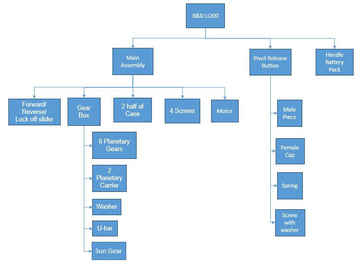
Product Structure
Model Drawings


Assembly Mistake Proofing
DFMA 1 (Design for Manufacturing/Assembly)
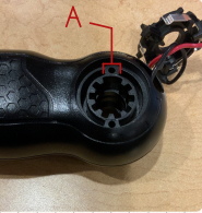
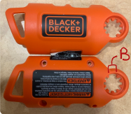
One design that Black & Decker used to prevent mistakes is to put a gap in the teeth as shown at A and B. The pivot button and cap have a corresponding larger tooth which fits into the slot, and can only fit into the assembly one way. This feature is important because it ensures that the cap will be flush with the case as designed and also ensures that the button will always return to its upright position.
DFMA 2


Another mistake proofing design is how the Forward/Reverse/Lock off slider connects to ring below. The slot only fits over the pin on the ring in one orientation. This is important because it ensures that the fins in the top left picture push down the metal contacts which connect to the motors terminals when you press on the slider.
DFMA 3

A third mistake proofing design is the joint connecting the handle and front assembly. There is a fin on the slot which fits into a slot in the handle. This ensures the handle only rotates 90 degrees in order to avoid damaging the wires inside and the plastic casing.
How It Works
Forward/Reverse/Lock off slider


The Forward/Reverse/Lock off slider is connected to the ring pictured above, which has two terminals coming from the battery on either side. The motor stick through from the opposite side so that its terminals are at the blue spots. At this point the drill is off. When the switch is turned clockwise the motor's terminals move to the green spots connecting it to the battery terminals and the screwdriver turns on. When turned the other way the motor's terminals go to the red spots and touch the opposite battery terminal as before. This causes the motor and thus the screwdriver to spin in the opposite direction.
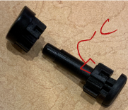
Handle Pivot Lock


The handle pivot works by interlocking teeth to stop the handle from turning. The button can be pushed in, so the teeth are no longer interlocked, and then the handle can be turned. A spring pushes on the button so that it is pushed back into the teeth when the button is release. The button goes through until the U tooth catches on the cases tooth and the system is locked. The fins shown in DFMA 3 make it so the handle can only go from a right angle to straight.
Power/Manual Control

The power/ manual control works by pushing a stationary gear up over the planetary carrier which spins the screwdriver. When the control is turned back the gear goes back off of the planetary carrier, allowing the screwdriver to spin again.
Conclusion
In this project I learned a lot and was also able to practice my skills with CAD. I have used electric screwdrivers a lot, but never knew how they worked so it was very interesting to find out. I think the most interesting thing I got out of this project was learning just how much you can increase torque in such small place. I was also intrigued by how they were able to use so few electronics and most of the features were mechanical, which I did not expect.


Comments